ENTERPRISE WI-FI ENGINEERING
Predictive RF modeling, engineered access point placement, and Ekahau-based validation for wireless networks that have to work — from first requirements through final walkthrough. Supporting organizations in Arizona and multi-site environments nationwide.
Professional Wi-Fi design is not a matter of counting square footage and spacing access points evenly across a floor plan. A network that actually performs starts with the business requirements behind it: which applications have to run reliably, how many devices and what kind — laptops, mobile phones, IoT sensors, handheld scanners — need to connect and where, what latency and throughput those applications demand, how devices need to roam between access points without dropping a call or a scan, and what the physical environment and construction actually look like. Design decisions made without that context tend to produce networks that show full signal bars and still fail under real load.
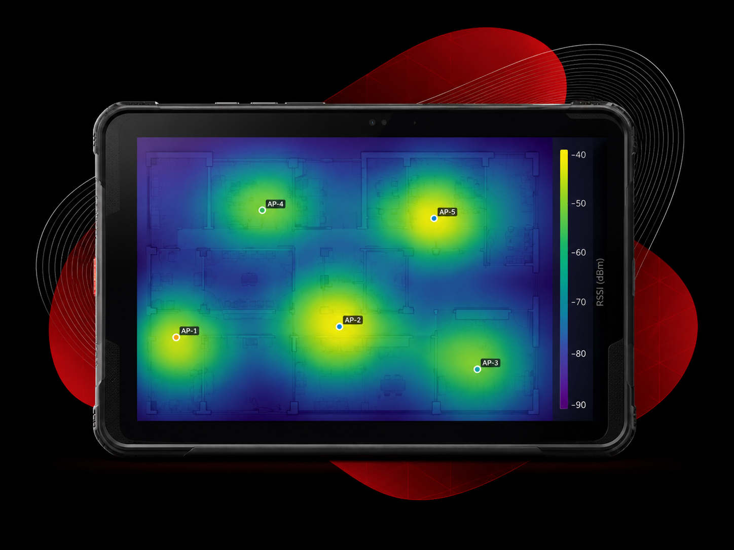
Before an access point is ordered, we build a predictive RF model of the space in Ekahau: the floor plan, wall and ceiling construction, and the specific AP models and antenna patterns being considered. That model simulates how signal actually propagates through the building — not an idealized open room, but the real one, including how wall materials and metal structures absorb, reflect, or distort a signal. AI-assisted modeling helps evaluate coverage, interference, and capacity scenarios before installation, so placement and mounting height decisions are based on how the space actually behaves rather than a rule of thumb.
Modern designs have to account for 2.4, 5, and 6 GHz, each with different spectrum availability, propagation characteristics, regulatory limits, and client support. Compared with 5 GHz, 6 GHz has modestly higher free-space path loss and can experience additional attenuation through some building materials. Material composition, thickness, angle, and moisture content can change that loss, which is why predictive assumptions should ultimately be validated in the real environment. Channel width, band steering, and client compatibility all factor into how a design balances capacity against coverage across bands, rather than just turning on every radio and hoping.
Where an access point goes should be determined by RF engineering, not by the nearest available ceiling tile or power outlet. Placement decisions weigh primary and secondary coverage overlap, signal-to-noise ratio, co-channel contention and adjacent-channel interference between neighboring APs, how client devices need to roam as people move through a space, and the capacity a given area needs to support. Coverage alone does not equal good design. A client can have strong RSSI and still perform poorly when airtime is congested, SNR is inadequate, cells overlap excessively, or roaming behavior is poorly matched to client capabilities. Dead zones and weak-performance areas often trace back to placement, attenuation assumptions, antenna choice, mounting, or environmental constraints — not simply the AP model.
Seeing an SSID and getting a strong signal reading is not the same as having a properly designed network. The question that actually matters is whether the network can support the number of devices and the application load in a given area at the same time — a conference room with forty laptops on a video call needs a fundamentally different design than an open warehouse floor with a handful of handheld scanners, even if both spaces are the same square footage. We go into more depth on designing for capacity instead of just coverage in our Insights section; it is one of the most consistent gaps we find in networks that were designed to a coverage map rather than a usage model.
Channel allocation and transmit power set the actual cell size of each access point and determine how much they contend with one another. Reusing channels too aggressively in a dense deployment causes co-channel contention; running every radio at full power can expand overlapping cells, increase co-channel contention, and make roaming less predictable instead of solving coverage problems. Transmit power should also be considered relative to client capability — if an AP can be heard much farther than a client can reliably transmit back, the result can be an asymmetric RF cell. A proper channel and power plan accounts for the RF environment, the number of APs in range of each other, and how the design needs to scale as the space or device count changes.
Wi-Fi 6E opened up the 6 GHz band, giving designs access to clean spectrum without the legacy congestion common on 2.4 and 5 GHz. Wi-Fi 7 builds on that with wider 320 MHz channels in the 6 GHz band and Multi-Link Operation, which can lower latency and increase throughput for clients that support it — but wider is not automatically better. In a dense deployment, running every access point at the widest available channel width reduces the number of non-overlapping channels left for reuse, which can increase co-channel contention and reuse pressure instead of improving performance. Whether 320 MHz channels make sense for a given design depends on spectrum availability, client density, existing interference, capacity requirements, and what the application load actually demands — not just what the newest standard supports. We go into more detail on what Wi-Fi 6E and 7 actually change versus what is marketing, and separately on how to validate Wi-Fi 7 performance in the field once it is installed.
Depending on project scope, design deliverables may include:
A predictive design is not the same as validation. A predictive design models the intended RF environment before deployment; post-install validation confirms what was actually built and measures the resulting network. Both matter, and neither substitutes for the other — see our Wi-Fi site survey and validation options for the second half of that process.

Ekahau ECSE-Design Certified
The predictive RF engineering covered on this page — requirements, modeling, placement, and channel planning.
On-site survey work confirming the installed network performs as designed. See our Wi-Fi site survey options.
Once a network is live, TekFidelityIQ provides ongoing visibility into how it performs over time.
A Wi-Fi design is predictive engineering performed before deployment: modeling the environment and planning AP placement, channels, power, and capacity. A site survey is measured RF work performed in the actual environment. Pre-deployment survey work can validate assumptions such as attenuation or proposed AP placement; post-install validation confirms how the installed network actually performs. See our Wi-Fi survey options.
No. Ekahau is the predictive modeling and survey platform TekFidelity uses, but the software is not the design. The quality of the result depends on requirements, model assumptions, RF engineering decisions, and validation.
Coverage means a signal reaches an area. Capacity means the network can support the number of devices and applications actually using that area at once. A design can have full coverage and still fail under real load if capacity was not part of the plan — see our note on designing for capacity, not just coverage.
No. TekFidelity is Arizona-based and supports predictive Wi-Fi design and multi-site projects nationwide. On-site survey and validation availability depends on project location and scope.
Tell us about your space, your devices, and what has to work reliably. We will walk you through what a proper design engagement looks like for your project.