

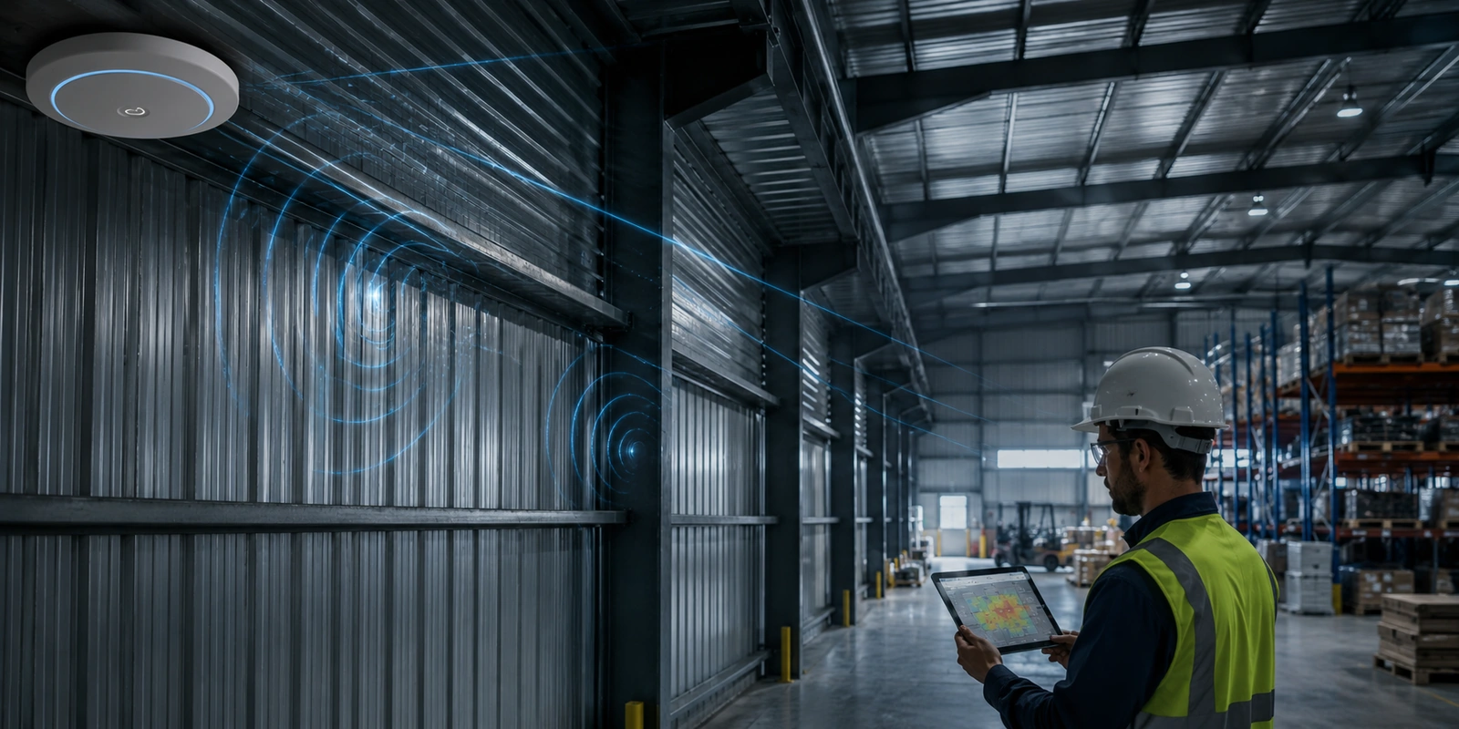
Metal doesn’t behave like drywall or concrete — it doesn’t mainly absorb Wi-Fi signal, it reflects it. That distinction is the difference between a design that accounts for the real failure mode in a metal building and one that treats it like any other dense-material problem and gets surprised by the result.
Why metal is a reflection problem, not an attenuation problem
Drywall and concrete mainly absorb RF energy as it passes through, so the design question is how much loss to budget for. Metal surfaces — corrugated siding, ductwork, racking, roll-up doors — mainly reflect it. That produces multipath: the same signal arriving at a client from several directions with different delays, which causes the signal to partially cancel itself out at specific points in the room, sometimes just a few feet apart. A survey done with a simple walk-test can show strong signal, then a null, then strong signal again over a short distance — that pattern is a multipath signature, not a coverage gap, and the fix for it is different from the fix for a coverage gap.
How this differs by band
2.4 GHz’s longer wavelength diffracts around metal obstructions somewhat better, but it also sets up standing waves more readily in a metal-walled space, producing the multipath nulls described above. 5 GHz reflects more directly off metal with less diffraction around it, producing cleaner shadows but also stronger, more localized reflections. 6 GHz’s much shorter wavelength is the least forgiving of the three — it’s effectively blocked by most metal structures rather than working around them, which means 6 GHz coverage in a metal building needs meaningfully tighter AP spacing than the same design would need on 5 GHz, not just a straight port of the 5 GHz plan.
Why antenna choice matters more here than in a typical office
A standard omnidirectional antenna (roughly 2-5 dBi gain) radiates in every direction, which is exactly what generates more reflections in a highly reflective metal environment. A directional or sector antenna (roughly 8-14 dBi gain, depending on beamwidth) concentrates energy toward the area that actually needs coverage and away from the metal surfaces most likely to reflect it back into the room as interference. In a metal building, the antenna pattern is often a bigger lever on real-world performance than raw transmit power.
How a real survey catches this before install
A predictive model alone can’t fully capture building-specific multipath behavior — it estimates attenuation well but doesn’t know exactly where a given roof’s corrugation pattern or a specific rack layout will create a standing-wave null. That’s what an on-site validation survey with a tool like Ekahau Sidekick is for: walking the actual space with real hardware, mapping where signal quality actually degrades, and confirming the antenna choice and AP placement hold up against the specific reflective geometry of that building, not just a generic “metal building” assumption.
What this means for AP density and placement
Expect a metal building’s real AP count to run higher than a drywall/concrete space of the same square footage at the same client density, and expect placement to favor directional coverage aimed away from large flat metal surfaces rather than a symmetric grid. Warehouses and manufacturing floors are the most common case, but any building with substantial exposed structural steel or metal roof decking shows the same pattern.
The practical takeaway
Treating a metal building like a denser version of a normal building misses the actual failure mode — reflection and multipath, not just extra attenuation. TekFidelity’s Predictive Wi-Fi Design accounts for this at the modeling stage, and on-site validation surveys confirm it against the building’s real geometry before the design is considered final.